
Internal Structure of an Air Handler Unit.
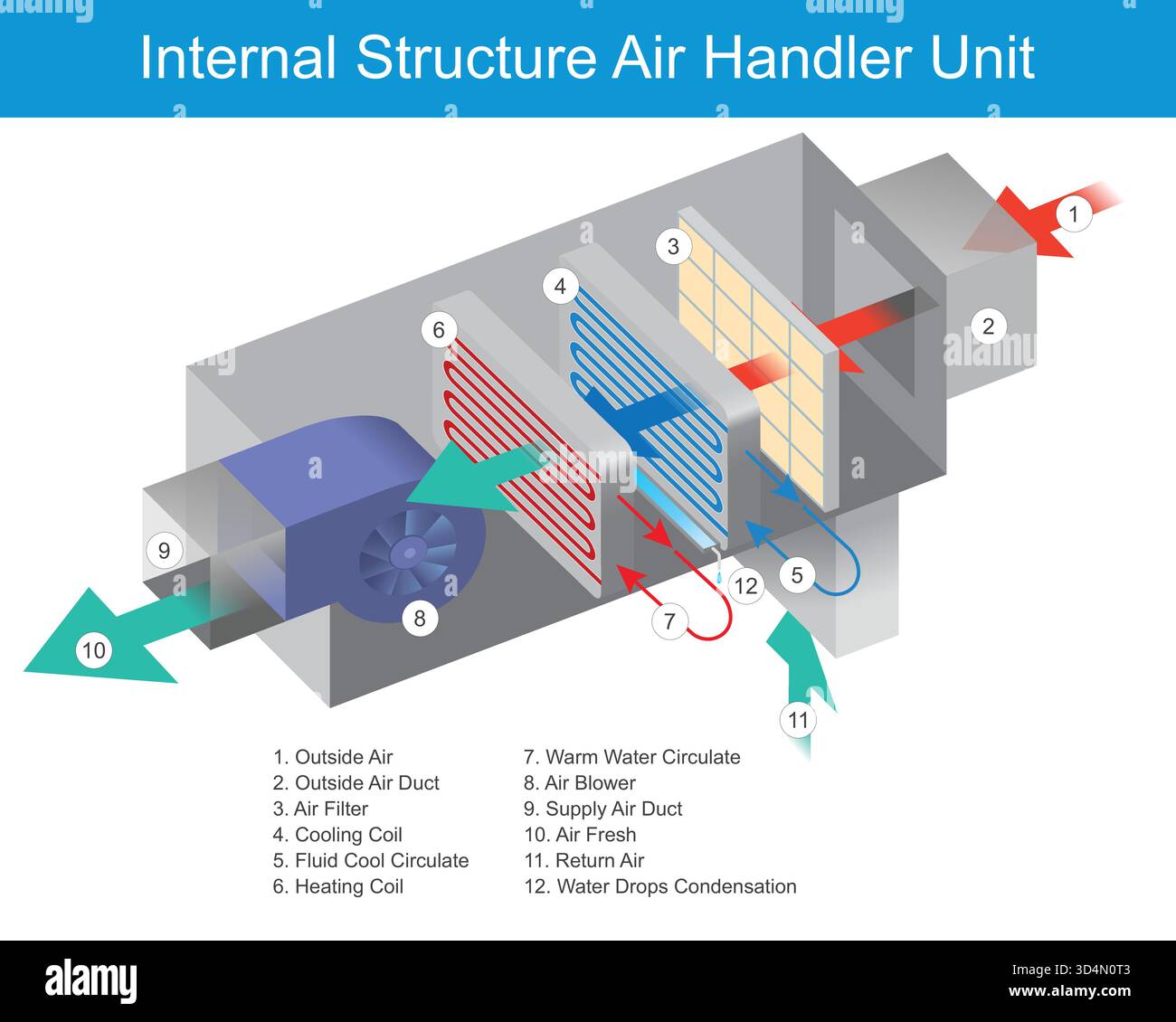
Image details
Contributor:
PATTARAWIT CHOMPIPATImage ID:
3D4N0T3Releases:
Model - no | Property - noDo I need a release?Date created:
13 November 2025Location:
ThailandMore information:
Access rights only. This is a handout or public domain image supplied by a third party. Ä¢¹½´«Ã½ grants access to the digital file but provides no warranties regarding copyright or moral rights. Alteration, modification, or cropping is prohibited without prior approval. All commercial uses require advance authorization from the content provider.
This diagram illustrates the internal components and operational flow of an Air Handler Unit (AHU). Air is pulled in from the outside (1) through a duct (2) and passes through an air filter (3) to remove particles. The air then moves across a cooling coil (4), which contains a chilled fluid (5) that cools the air, and a heating coil (6), which contains warm water (7) that can heat the air. As the air cools, condensation (12) is produced. An air blower (8) circulates the processed air into a supply duct (9) where it is distributed as fresh air (10) into a building. Return air (11) from the building is also pulled back into the unit to be reconditioned.

